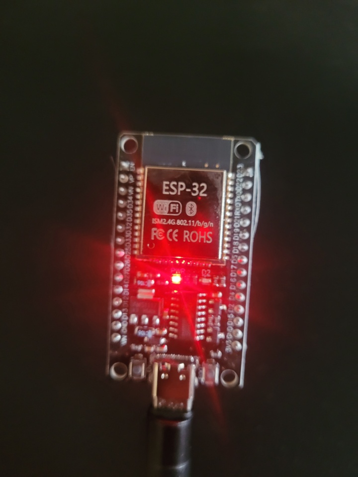
👉🏻 보드 모델 / board model: ESP32 WROOM 32 USB C Type CH340 Driver
👉🏻 먼저 ESP32와 맥OS와 연결합니다.
First, connect the ESP32 to macOS.
👉🏻 아두이노 IDE를 다운로드하고 설치합니다.
Download and install the Arduino IDE.
https://www.arduino.cc/en/software/#ide
👉🏻 아두이노 IDE에 ESP32 인식을 위한 셋팅을합니다.
Set up Arduino IDE to recognize ESP32.
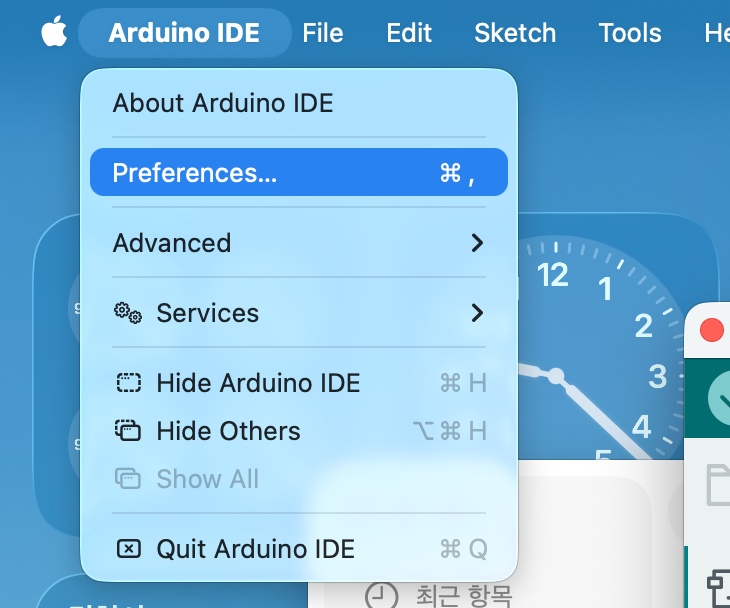
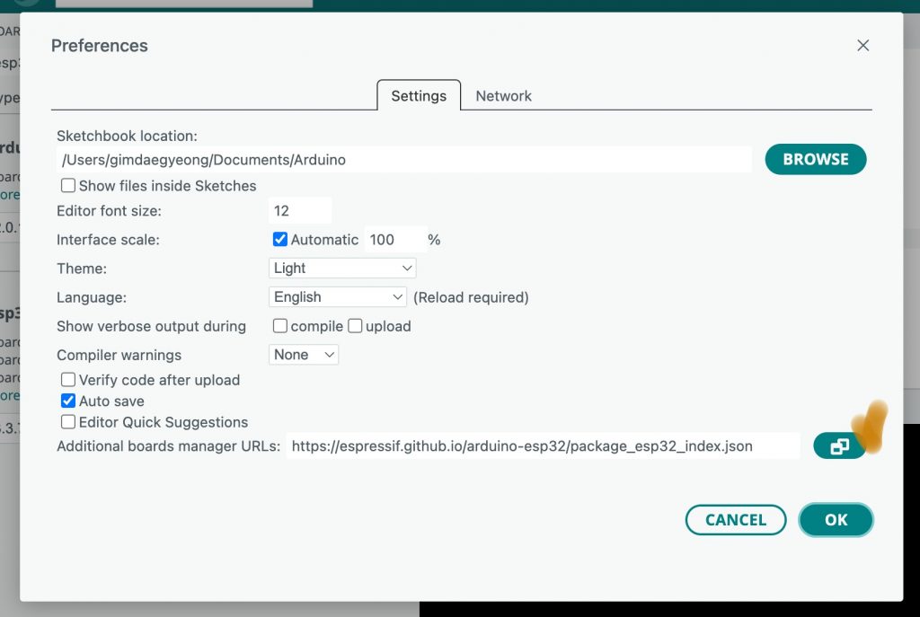
✔️ Arduino IDE -> Preferences…선택
Select Arduino IDE -> Preferences…
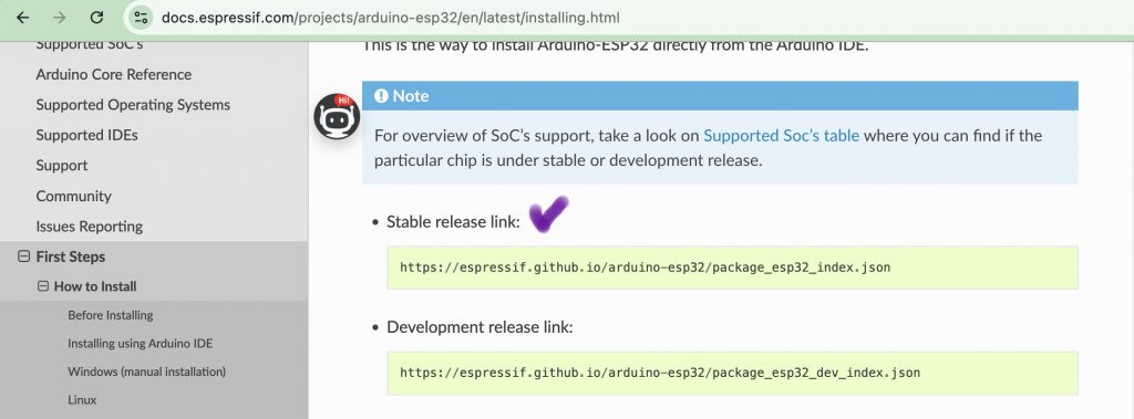
✔️ ESP32 드라이버 설치 / Installing the ESP32 driver
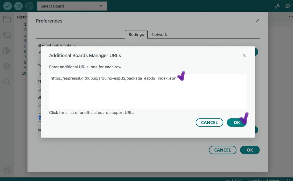
— 아래의 웹사이트에서 stable위치의 링크를 아두이노 IDE에 적용해서 드라이버를 설치합니다.
Install the driver by applying the link in the stable location on the website below to Arduino IDE.
https://docs.espressif.com/projects/arduino-esp32/en/latest/installing.html
— 아두이노 IDE에 위의 웹사이트 링크를 붙여넣습니다.
Paste the website link above into your Arduino IDE.
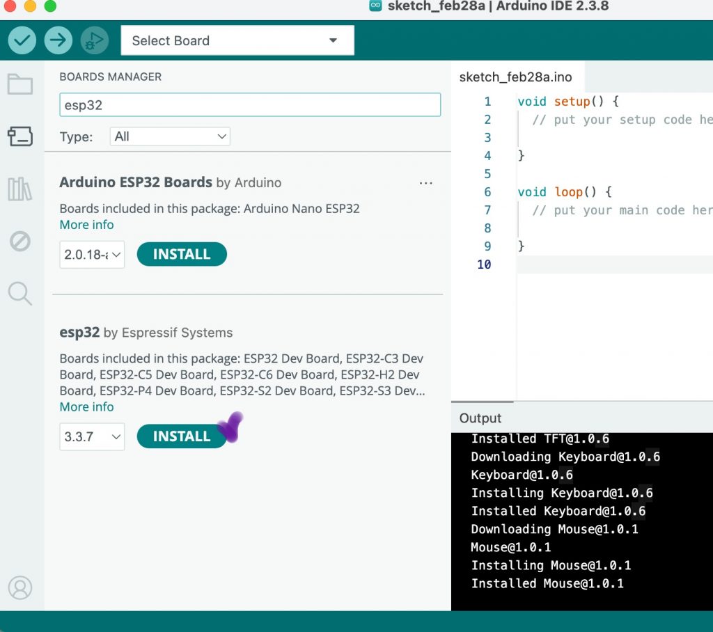
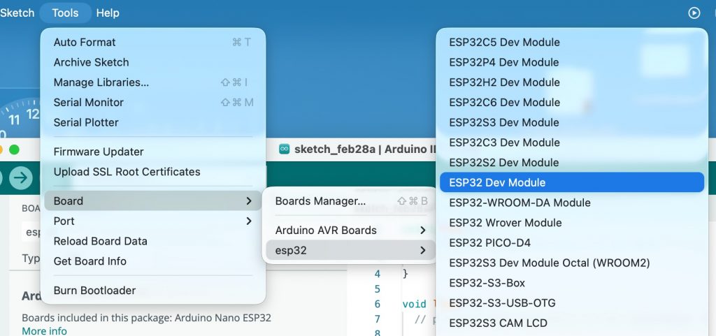
— Tools -> Board ->Boardmanager를 선택하면 아래와 같은 화면을 볼 수 있습니다.
If you select Tools -> Board -> Boardmanager, you will see the screen below.
— 여기서 esp32 by Espressif Systems를 선택합니다
Here we select esp32 by Espressif Systems
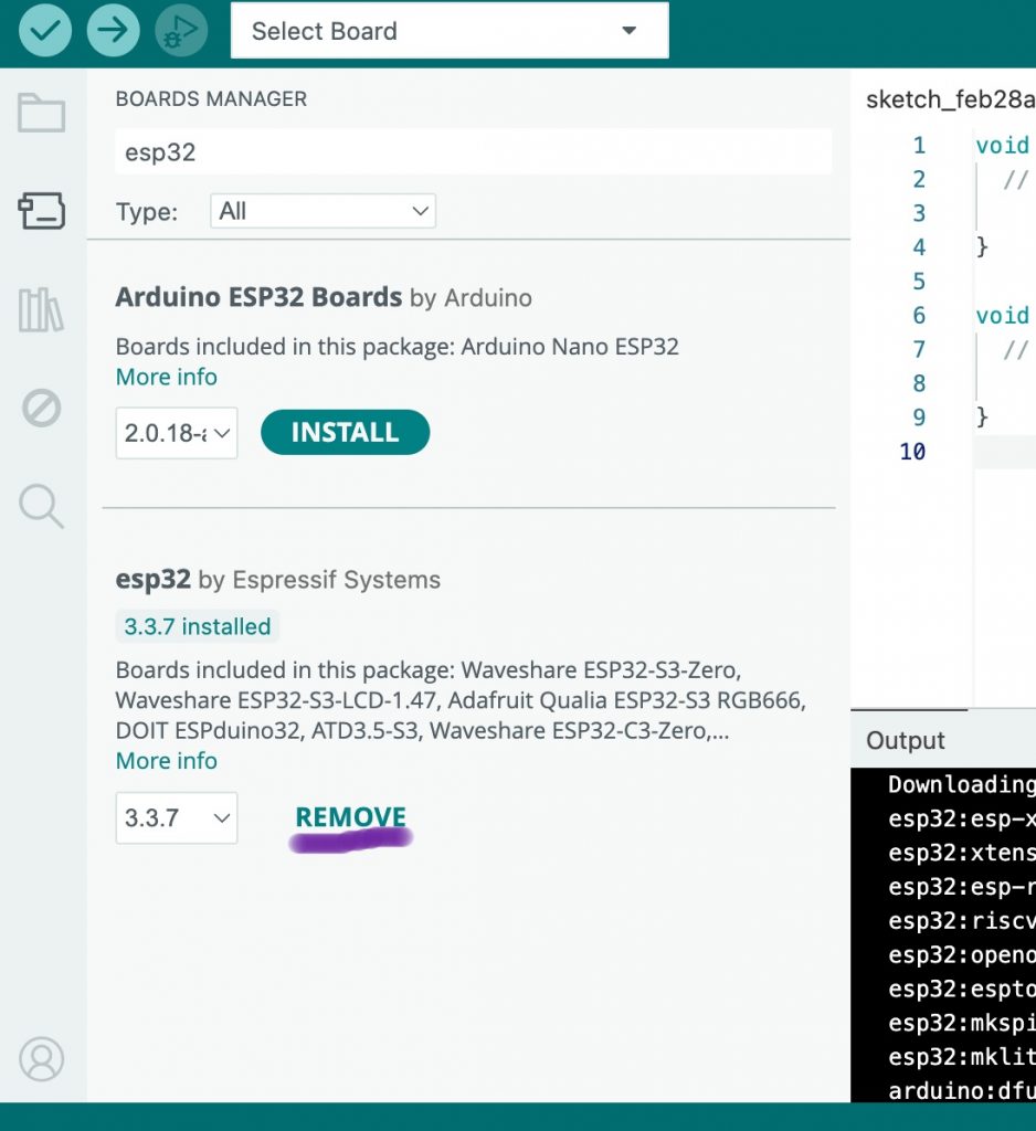
— 설치가 완료되면 버튼이름이 remove로 바뀝니다.
Once installation is complete, the button name will change to remove.
👉🏻 아두이노 IDE에 포함된 예제 코드를 실행합니다.
Run the example code included in the Arduino IDE.
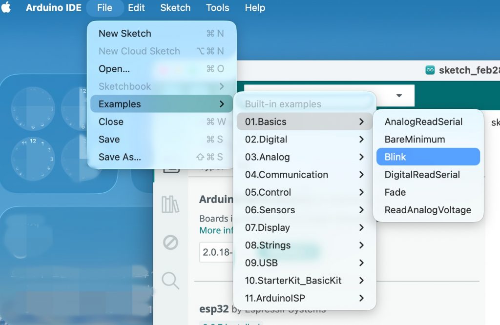
✔️ File->Examples->01.Basics-> Blink를 선택합니다.
Select File->Examples->01.Basics-> Blink.
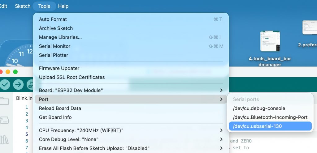
👉🏻 설치된 드라이버와 포트를 선택합니다.
Select the installed driver and port.
✔️ 드라이버선택 / Select driver
✔️ 포트 선택 / Port selection
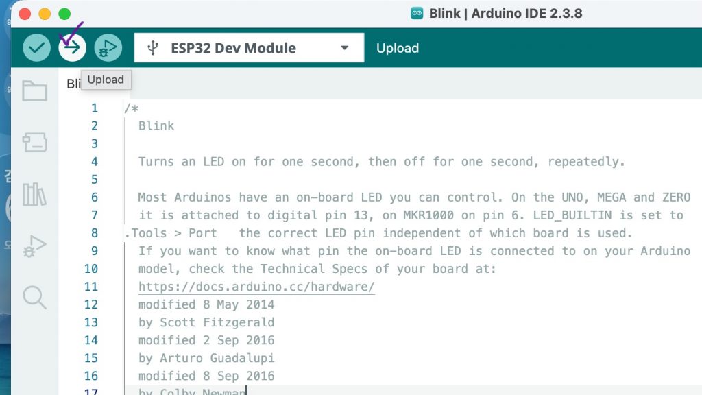
👉🏻 코드 업로드 및 실행 / Upload and run code
✔️ -> 버튼을 클릭해서 코드를 보드에 업로드합니다.
-> Click the button to upload the code to the board.
⭐️ 만약에 코드 실행중 오류 나면 아래처럼 코드를 수정해야합니다.
If an error occurs while running the code, you need to modify the code as below.
/*
  Blink

  Turns an LED on for one second, then off for one second, repeatedly.

  Most Arduinos have an on-board LED you can control. On the UNO, MEGA and ZERO
  it is attached to digital pin 13, on MKR1000 on pin 6. LED_BUILTIN is set to
.Tools > Port   the correct LED pin independent of which board is used.
  If you want to know what pin the on-board LED is connected to on your Arduino
  model, check the Technical Specs of your board at:
  https://docs.arduino.cc/hardware/
  modified 8 May 2014
  by Scott Fitzgerald
  modified 2 Sep 2016
  by Arturo Guadalupi
  modified 8 Sep 2016
  by Colby Newman

  This example code is in the public domain.

  https://docs.arduino.cc/built-in-examples/basics/Blink/
*/

// 2번 핀을 LED 핀으로 정의합니다.(코드 바뀐 부분)
#define LED_BUILTIN 2

// the setup function runs once when you press reset or power the board
void setup() {
  // initialize digital pin LED_BUILTIN as an output.
  pinMode(LED_BUILTIN, OUTPUT);
}

// the loop function runs over and over again forever
void loop() {
  digitalWrite(LED_BUILTIN, HIGH);  // change state of the LED by setting the pin to the HIGH voltage level
  delay(1000);                      // wait for a second
  digitalWrite(LED_BUILTIN, LOW);   // change state of the LED by setting the pin to the LOW voltage level
  delay(1000);                      // wait for a second
}
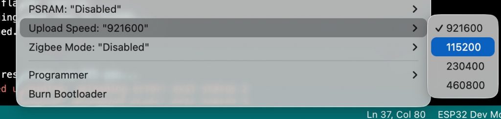
⭐️ 업도드 속도 때문에오류가 난다면 아래처럼 전송속도를 낮춥니다.
If an error occurs due to the upload speed, lower the transfer speed as shown below.
✔️ Tools->UploadSpeed->11520
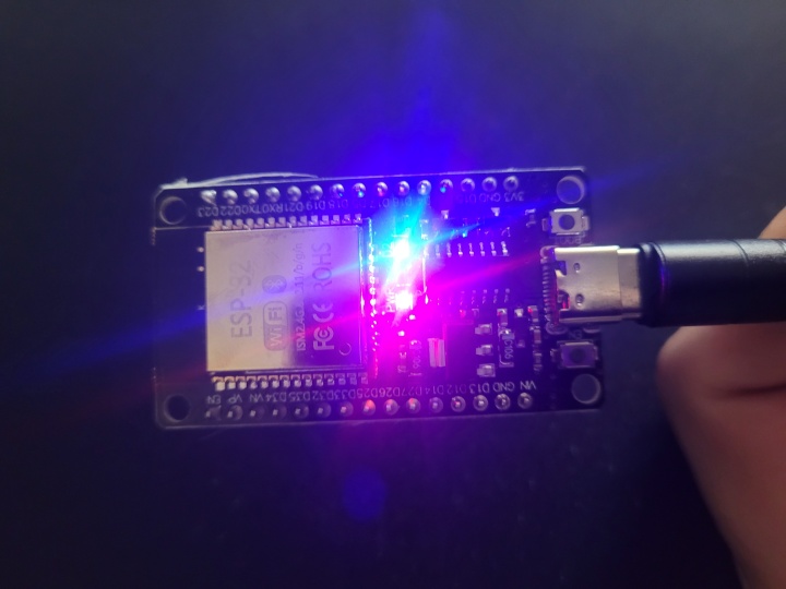
👉🏻 위의 과정이 모두 정상적으로 실행되면 Esp32 보드의 LED가 깜빡이는 것을 볼 수 있습니다.
If all the above processes are executed normally, you will see the LED on the Esp32 board blinking.