👉️ 32비트 보호모드로 전환하는 부분입니다.
This is the part where the system switches to 32-bit protected mode.
👉️ 16비트에서 그래픽 모드로 설정하고 32비트 보호모드로 전환후에 화면에 핑크색 사각형을 그리는 코드입니다.
This code sets the system to 16-bit graphics mode, switches to 32-bit protected mode, and then draws a pink rectangle on the screen.
👉️ 전체 코드 / Full Code
✔️ boot.asm
— jmp 0x8000 이 코드를 아래처럼 수정했습니다.
I modified the jmp 0x8000 code as shown below.
— 나머지는 이 전과 같아 설명을 생략합니다.
The rest is the same as before, so I will omit the explanation.
jmp 0x0000:0x8000✔️ sector2.asm
[org 0x8000]
bits 16

start:
    ; --------------------------------────────────────----
    ; 1. A20 게이트 활성화 (키보드 컨트롤러 이용한 표준 방식)
    ; 1. Enable A20 Gate (Standard method using keyboard controller)
    ; --------------------------------────────────────----
    in al, 0x92
    or al, 2
    out 0x92, al

    ; ----------------------------------------------------
    ; 2. GDT(Global Descriptor Table) 정보를 CPU에 로드
    ; 2. Load GDT (Global Descriptor Table) information into CPU
    ; ----------------------------------------------------
    cli                 ; 32비트 전환 중 방해받지 않도록 하드웨어 인터럽트 금지
                        ; Disable hardware interrupts to avoid interruption during 32-bit transition
    lgdt [gdt_pointer]  ; GDT 구조체의 주소를 CPU에 로드
                        ; Load the address of the GDT structure into the CPU

    ; ----------------------------------------------------
    ; 3. CR0 레지스터를 설정하여 32비트 보호 모드 활성화
    ; 3. Set CR0 register to enable 32-bit Protected Mode
    ; ----------------------------------------------------
    mov eax, cr0        ; CR0 레지스터 값을 일반 레지스터로 가져옴
                        ; Load the CR0 register value into a general-purpose register.

    or eax, 0x00000001  ; 0번째 비트(PE: Protection Enable)를 1로 설정
                        ; Set the 0th bit (PE: Protection Enable) to 1.
    mov cr0, eax        ; 변경된 값을 다시 CR0에 적용 (이 순간 32비트 모드 활성화!)
                        ; Apply the modified value back to CR0 (32-bit mode is activated at this moment!)

    ; ----------------------------------------------------
    ; 4. 32비트 세그먼트 영역으로 멀리뛰기(Far Jump)
    ; 4. Far Jump into 32-bit segment region
    ; ----------------------------------------------------
    ; 0x08은 아래 GDT에서 정의한 32비트 코드 세그먼트의 위치(오프셋)입니다.
    ; 0x08 is the offset of the 32-bit code segment defined in the GDT below.
    jmp 0x08:protected_start


; ====================================================
; 여기서부터는 완전히 32비트 기계어로 실행되는 구역입니다!
; From here, the code executes completely in 32-bit machine code!
; ====================================================
bits 32

protected_start:
    ; 32비트용 데이터 세그먼트 레지스터들 초기화 (GDT의 0x10 오프셋 사용)
    ; Initialize 32-bit data segment registers (Using 0x10 offset from GDT)
    mov ax, 0x10
    mov ds, ax
    mov es, ax
    mov fs, ax
    mov gs, ax
    mov ss, ax

    ; ----------------------------------------------------
    ; 5. [32비트 C언어 스타일 테스트] 비디오 메모리에 직접 사각형 그리기
    ; 5. [32-bit C-style Test] Draw a rectangle directly to Video Memory
    ; ----------------------------------------------------
    ; BIOS를 못 쓰므로 그래픽 모드(VRAM) 주소인 0xA0000에 포인터처럼 직접 데이터를 씁니다.
    ; Since BIOS is unavailable, write data directly to 0xA0000 (VRAM address) like a pointer.

    mov edi, 0xA0000    ; 비디오 메모리 시작 물리 주소
                        ; Video memory starting physical address

    ; 가로 100, 세로 50 위치 계산: (50 * 320) + 100 = 16100
    ; Calculate position for X=100, Y=50: (50 * 320) + 100 = 16100
    add edi, 16100

    mov edx, 0          ; Y 루프 카운터 (세로 30줄)
                        ; Y loop counter (30 rows)

draw_32bit_row:
    mov ecx, 0          ; X 루프 카운터 (가로 50칸)
                        ; X loop counter (50 columns)

draw_32bit_col:
    mov byte [edi], 12  ; 색상 번호 대입 (12 = 빨간색)
                        ; Assign color number (12 = Red)
    inc edi             ; 다음 픽셀 주소로 이동
                        ; Move to the next pixel address
    inc ecx
    cmp ecx, 50
    jl draw_32bit_col

    ; 가로 한 줄을 다 그렸으면, 다음 줄의 시작점으로 EDI 포인터 건너뛰기
    ; After drawing one row, skip EDI pointer to the start of the next row
    ; 한 줄이 320픽셀인데 방금 50픽셀을 전진했으므로, 남은 270픽셀만큼 더해줍니다.
    ; Since a single line is 320 pixels and we have just advanced 50 pixels, we add the remaining 270 pixels.
    add edi, 270

    inc edx
    cmp edx, 30
    jl draw_32bit_row

    ; 작업 완료 후 무한 대기
    ; Infinite loop after work completion
    jmp $


; ----------------------------------------------------
; 데이터 영역: GDT(Global Descriptor Table) 구조 정의
; Data Area: Define GDT (Global Descriptor Table) Structure
; ----------------------------------------------------
align 4

gdt_start:
    ; 1. 널 디스크립터 (하드웨어 규격상 필수적인 빈 슬롯)
    ; 1. Null Descriptor (Mandatory empty slot by hardware specification)
    dd 0, 0

    ; 2. 코드 세그먼트 디스크립터 (오프셋 0x08): 전체 4GB 영역, 읽기/실행 가능
    ; 2. Code Segment Descriptor (Offset 0x08): Full 4GB range, Read/Execute allowed
    dw 0xFFFF, 0x0000
    db 0x00, 0x9A, 0xCF, 0x00

    ; 3. 데이터 세그먼트 디스크립터 (오프셋 0x10): 전체 4GB 영역, 읽기/쓰기 가능
    ; 3. Data Segment Descriptor (Offset 0x10): Full 4GB range, Read/Write allowed
    dw 0xFFFF, 0x0000
    db 0x00, 0x92, 0xCF, 0x00
gdt_end:

; CPU에 GDT 위치를 전달하기 위한 포인터 구조체 (6바이트 크기)
; Pointer structure to deliver GDT position to CPU (6 bytes size)
gdt_pointer:
    dw gdt_end - gdt_start - 1  ; GDT의 크기 (Size of GDT)
    dd gdt_start                ; GDT의 시작 주소 (Starting address of GDT)

; 512바이트 크기 맞추기
; Pad to 512 bytes
times 512 - ($ - $$) db 0
👉️ 컴파일 / Compiling
nasm -f bin boot.asm -o boot.bin
nasm -f bin sector2.asm -o sector2.bin
cat boot.bin sector2.bin > temp.bin
dd if=temp.bin of=os.img bs=512 count=2880 conv=sync
qemu-system-x86_64 -drive file=os.img,format=raw,if=floppy -boot a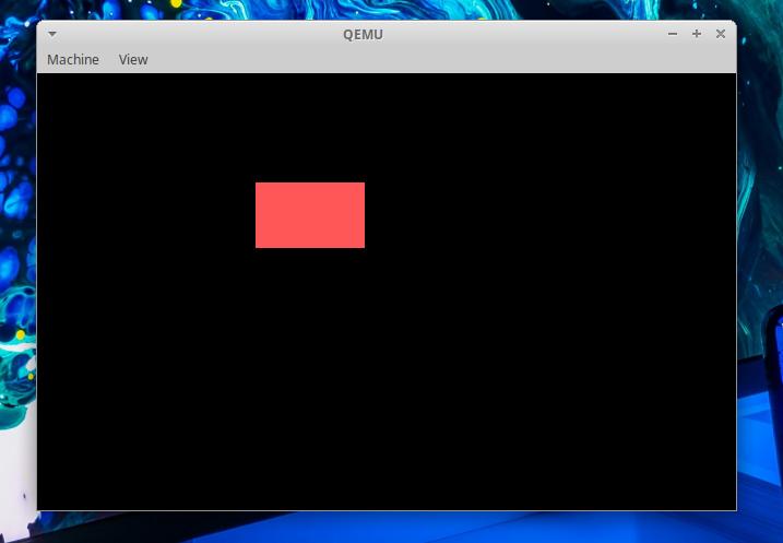
👉️ 코드 설명 / Code Explanation
✔️ 1MB 이상의 상위 메모리 영역(System Memory)을 사용하기 위해 ‘A20 게이트(A20 Gate)’라는 하드웨어 빗장을 푸는 코드입니다.
This is code that unlocks the hardware mechanism known as the ‘A20 Gate’ to enable the use of memory areas (system memory) above the 1MB mark.
    in al, 0x92
    or al, 2
    out 0x92, al
— 이 설정으로 1MB이상 메모리를 사용할 수 있습니다.(최대 4기가 바이트까지 사용가능)
With this setting, you can use more than 1 MB of memory (up to a maximum of 4 GB).
— 32비트 보호 모드에서 사용할 수 있는 최대 메모리가 4기가바이트(4GB)인 이유는, 32비트 CPU가 한 번에 가리킬 수 있는 방 번호(메모리 주소)의 총개수가 딱 4,294,967,296개이기 때문입니다.
The reason the maximum memory available in 32-bit protected mode is 4 gigabytes (4GB) is that the total number of room numbers (memory addresses) a 32-bit CPU can reference at once is exactly 4,294,967,296.
— 32비트가 나타낼 수 있는 주소: 2³² = 4,294,967,296개
Addresses representable by 32 bits: 2³² = 4,294,967,296
— in al, 0x92
시스템 제어 포트(0x92)에서 현재 설정 상태를 1바이트 읽어 AL 레지스터에 저장합니다.
Read the current setting status (1 byte) from system control port 0x92 and store it in the AL register.
— or al, 2
AL 레지스터의 값 중 ‘2번째 비트'(이진수로 00000010)를 1로 강제 전환합니다.
Force the ‘second bit’ (00000010 in binary) of the AL register’s value to 1.
1) al과 2의값을 or연산 합니다.(예)
Perform an OR operation on the values of AL and 2. (Example)
0x92 포트(port) = 00101001

AL         00101001
2          00000010
-------------------
결과(result)00101011
— out 0x92, al
변경된 설정 값을 다시 포트 0x92에 보내서 하드웨어에 적용합니다.
The modified setting values are sent back to port 0x92 to apply them to the hardware.
out 0x92, al✔️ GDT(Global Descriptor Table) 정보를 CPU에 로드
Load GDT (Global Descriptor Table) information into CPU
    cli                 ; 32비트 전환 중 방해받지 않도록 하드웨어 인터럽트 금지
                        ; Disable hardware interrupts to avoid interruption during 32-bit transition
    lgdt [gdt_pointer]  ; GDT 구조체의 주소를 CPU에 로드
                        ; Load the address of the GDT structure into the CPU
— cli : Clear Interrupt Flag
CPU가 하드웨어 인터럽트를 받지 않도록 설정하는 명령입니다.
This is a command that configures the CPU not to accept hardware interrupts.
— lgdt [gdt_pointer]
1)32비트 모드(보호모드)에서는 보호 모드에서는 세그먼트 레지스터의 값이 GDT의 엔트리를 가리키는 선택자(Selector)가 되며, CPU는 GDT에서 실제 메모리 시작 주소(Base), 크기(Limit), 접근 권한 등을 찾아 사용합니다.
2)세그먼트 레지스터(CS, DS, SS 등)는 이 GDT를 기준으로 해석라고 알려주는 것입니다.
Segment registers (such as CS, DS, and SS) are configured to be interpreted based on this GDT.
✔️ CR0 레지스터를 설정하여 32비트 보호 모드 활성화
Set CR0 register to enable 32-bit Protected Mode
— CS(Code Segment) :
기계어가 저장된 메모리의 위치를 찾는 데 사용되는 레지스터
A register used to locate the memory address where machine code is stored.
— cr0에 직접 값을 입력 할 수 없습니다.
You cannot directly assign a value to cr0.
— cr0는 제어레지스트로 다른 비트들이 들어 있기 때문에 기존 값을 읽어와서 0번째 비트 (PE:Protection Enable)값만 바꿉니다.
Since cr0 is a control register containing other bits, you must read the existing value and modify only the 0th bit (PE: Protection Enable).
    mov eax, cr0        ; CR0 레지스터 값을 일반 레지스터로 가져옴
                        ; Load the CR0 register value into a general-purpose register.

    or eax, 0x00000001  ; 0번째 비트(PE: Protection Enable)를 1로 설정
                        ; Set the 0th bit (PE: Protection Enable) to 1.
    mov cr0, eax        ; 변경된 값을 다시 CR0에 적용 (이 순간 32비트 모드 활성화!)
                        ; Apply the modified value back to CR0 (32-bit mode is activated at this moment!)
✔️ protected_start라벨로 far jump합니다.
Perform a far jump to protected_start.
jmp 0x08:protected_start— BIOS(리얼 모드)에서 사용하던 세그먼트 주소 계산 방식이 보호 모드에서는 더 이상 사용되지 않기 때문에, CPU가 사용할 새로운 세그먼트 정보(GDT)를 lgdt로 등록합니다.
Since the segment address calculation method used in BIOS (real mode) is no longer employed in protected mode, the lgdt instruction is used to register the new segment information (GDT) for the CPU.
— 0x08는 리얼모드에서 사용하던 cs값을 GDT의 선택자로 바꿉니다.
0x08 replaces the CS value used in real mode with a GDT selector.
— 0x08는더 이상 주소 값이 아닌 GDT의 선택자가 됩니다.
0x08 is no longer an address value but becomes a GDT selector.
— 리얼모드(16비트) : CS = 실제 세그먼트 주소
Real Mode (16-bit): CS = Actual segment address
— 보호모드(32비트) : CS = GDT의 코드 세그먼트 선택자
Protected Mode (32-bit): CS = Code segment selector from the GDT
— GDT의 구조
Structure of the GDT
- GDT구조 / GDT Structure
Entry0
Null Descriptor
주소 / Address
0x00

Entry1
Code Segment
주소 / Address
0x08

Entry2
Data Segment
주소 / Address
0x10

- GDT 그림 / GDT diagram
+----------------+
|0x00 Null       |
+----------------+
|0x08 Code       | ◀──── CS
+----------------+
|0x10 Data       |
+----------------+
✅ 다음 포스트에서 계속됩니다.
To be continued in the next post.


